Z-Buffering is the only rendering algorithm which is hardware accelerated by a widely available and affordable component: the GPU. For a long time, GPUs could only synthesize triangles, and since there was no other way of generating images in real-time, performance critical applications used triangle meshes to describe their objects and render them. This is still mostly the case today, especially for video games. Although triangle meshes can reproduce any kind of surface, GPUs can only render them efficiently for a single scale/viewing distance: we get lack of detail above this scale, and aliasing below(
*). On modern hardware, subdivision surfaces - called patches in OpenGL4 - can limit the magnification problem to a certain extent. Today I'll introduce PN triangles and Phong tessellation, algorithms which try to solve this matter, and can be implemented in hardware using GLSL's tessellation control and evaluation shaders available with OpenGL4. Both of these algorithms are easy to implement and can be used transparently with "conventionnal" triangle meshes.
(
*) GPUs are also very inefficient when it comes to synthesizing polygons which have a size lower than a few pixels, also called micropolygons. This is why minification scenarios should be avoided when rendering with GPU rasterizers : they generate aliased images at sub optimal speed. That's something I'll probably detail in another article :-).
Brief overview of tessellation in OpenGL4
OpenGL4 adds a new pipeline for geometry processing which is specifically intended for patch primitives. It has two additional programmable processing stages: the tessellation control stage and the tessellation evaluation stage.
Tessellation control stage
The tessellation control stage can be programmed using GLSL's tessellation control shading language, or replaced by calls to the
glPatchParameter function. Its main goal is to provide subdivision levels to a tessellator (implemented in specific hardware in OpenGL4 GPUs) which performs the actual subdivision later in the pipeline. It is important to note that when using the programmable approach, the shader is executed for each vertex of the input patch (clearly for performance reasons, as this model allows to evaluate the data in parallel). This means that per patch varyings are evaluated several times, so heavy computations should be avoided or limited if possible (see the code of the shaders I present for an example).
Tessellation evaluation stage
The tessellation evaluation stage begins once the hardware tessellator has finished subdividing a patch, and has to be programmed using GLSL's tessellation evaluation shading language. This is the stage where the new vertices can be assigned their own attributes, using information provided by the tessellator and/or varyings from previous stages.
Curved PN triangles
The Curved PN triangle was first introduced in 2001 in a paper called
"Curved PN Triangles
". This primitive can be built from a regular triangle (composed of three vertices and their normals) to produce a richer description than triangle meshes, which combines a displacement field and a normal field.
Displacement field
Let a triangle be defined by 3 vertices $V_i = (P_i, N_i)$, where $P_i$ is the position and $N_i$ the normalized normal of the
ith vertex. The displacement field $b(u,v)$ of a PN Triangle is defined as follows:
\[\begin{align}b(u,v)&=\sum_{i+j+k=3}b_{ijk}\frac{3!}{i!j!k!}u^i v^j w^k\\&=b_{300}w^3 + b_{030}u^3 + b_{003}v^3\\ &+ b_{210}3w^2u + b_{120}3wu^2 + b_{201}3w^2v \\ &+ b_{021}3u^2v + b_{102}3wv^2 + b_{012}3uv^2 \\ &+ b_{111}6wuv \end{align}\]
where $(u, v, w)$ are the barycentric coordinates relative to the vertices, and the terms $b_{ijk}$ are the control points of the PN Triangle. If we define $w_{ij} = (P_j - P_i) \cdot N_i $, then the control points verify:
| \[\begin{align}&b_{300}= P_1 \\ &b_{030}= P_2 \\ &b_{003}= P_3 \\ &b_{210} = \frac{1}{3}(2P_1 + P_2 - w_{12}N_1) \\ &b_{120} = \frac{1}{3}(2P_2 + P_1 - w_{21}N_2) \\ &b_{021} = \frac{1}{3}(2P_2 + P_3 - w_{23}N_2) \\ &b_{012} = \frac{1}{3}(2P_3 + P_2 - w_{32}N_3) \\ &b_{102} = \frac{1}{3}(2P_3 + P_1 - w_{31}N_3) \\ &b_{201} = \frac{1}{3}(2P_1 + P_3 - w_{13}N_1) \\ &b_{111} = E + \frac{1}{2}(E - V) \end{align}\] |
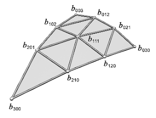 |
| Figure 1: Control points of the PN Triangles. |
|
with $E = \frac{1}{6} (b_{210}+b_{120}+b_{021}+b_{012}+b_{102}+b_{201})$, and $V = \frac{1}{3}(P_1+P_2+P_3)$.
Normal field
The normal field is described by a quadratic function $n(u,v)$ which is defined as:
\[\begin{align} n(u,v) &=\sum_{i+j+k=2}n_{ijk}u^i v^j w^k \\ &= n_{200}w^2 + n_{020}u^2 + n_{002}v^2 \\ &+ n_{110}wu + n_{011}uv + n_{101}wv \end{align}\]
By defining $v_{ij} = 2 \frac{(P_j-P_i)\cdot(N_i + N_j)}{(P_j-P_i)\cdot(P_j-P_i)}$, we have:
\[\begin{align} &n_{200}= N_1 \\ &n_{020}= N_2 \\ &n_{002}= N_3 \\ &n_{110}= \frac{N_1 + N_2 - v_{12}(P_2-P_1)}{\|N_1 + N_2 - v_{12}(P_2-P_1)\|} \\ &n_{011}= \frac{N_2 + N_3 - v_{23}(P_3-P_2)}{\|N_2 + N_3 - v_{23}(P_3-P_2)\|} \\ &n_{011}= \frac{N_3 + N_1 - v_{31}(P_1-P_3)}{\|N_3 + N_1 - v_{31}(P_1-P_3)\|}\end{align}\]
|
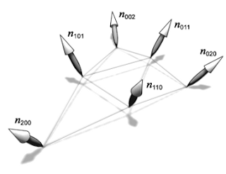 |
| Figure 2: Normal components of the PN Triangles. |
|
GPU implementation
Now that we have the required equations to build the PN triangles, let's see how to implement this on the GPU. I'll just give the code of the two shaders and comment on what they're doing.
Here
's the the tessellation control shader
code:
#version 420 core

// PN patch data
struct PnPatch
{
 float b210;
 float b120;
 float b021;
 float b012;
 float b102;
 float b201;
 float b111;
 float n110;
 float n011;
 float n101;
};

// tessellation levels
uniform float uTessLevels;

layout(vertices=3) out;

layout(location = 0) in vec3 iNormal[];
layout(location = 1) in vec2 iTexCoord[];

layout(location = 0) out vec3 oNormal[3];
layout(location = 3) out vec2 oTexCoord[3];
layout(location = 6) out PnPatch oPnPatch[3];

float wij(int i, int j)
{
 return dot(gl_in[j].gl_Position.xyz - gl_in[i].gl_Position.xyz, iNormal[i]);
}

float vij(int i, int j)
{
 vec3 Pj_minus_Pi = gl_in[j].gl_Position.xyz
                  - gl_in[i].gl_Position.xyz;
 vec3 Ni_plus_Nj  = iNormal[i]+iNormal[j];
 return 2.0*dot(Pj_minus_Pi, Ni_plus_Nj)/dot(Pj_minus_Pi, Pj_minus_Pi);
}

void main()
{
 // get data
 gl_out[gl_InvocationID].gl_Position = gl_in[gl_InvocationID].gl_Position;
 oNormal[gl_InvocationID]            = iNormal[gl_InvocationID];
 oTexCoord[gl_InvocationID]          = iTexCoord[gl_InvocationID];

 // set base
 float P0 = gl_in[0].gl_Position[gl_InvocationID];
 float P1 = gl_in[1].gl_Position[gl_InvocationID];
 float P2 = gl_in[2].gl_Position[gl_InvocationID];
 float N0 = iNormal[0][gl_InvocationID];
 float N1 = iNormal[1][gl_InvocationID];
 float N2 = iNormal[2][gl_InvocationID];

 // compute control points
 oPnPatch[gl_InvocationID].b210 = (2.0*P0 + P1 - wij(0,1)*N0)/3.0;
 oPnPatch[gl_InvocationID].b120 = (2.0*P1 + P0 - wij(1,0)*N1)/3.0;
 oPnPatch[gl_InvocationID].b021 = (2.0*P1 + P2 - wij(1,2)*N1)/3.0;
 oPnPatch[gl_InvocationID].b012 = (2.0*P2 + P1 - wij(2,1)*N2)/3.0;
 oPnPatch[gl_InvocationID].b102 = (2.0*P2 + P0 - wij(2,0)*N2)/3.0;
 oPnPatch[gl_InvocationID].b201 = (2.0*P0 + P2 - wij(0,2)*N0)/3.0;
 float E = ( oPnPatch[gl_InvocationID].b210
           + oPnPatch[gl_InvocationID].b120
           + oPnPatch[gl_InvocationID].b021
           + oPnPatch[gl_InvocationID].b012
           + oPnPatch[gl_InvocationID].b102
           + oPnPatch[gl_InvocationID].b201 ) / 6.0;
 float V = (P0 + P1 + P2)/3.0;
 oPnPatch[gl_InvocationID].b111 = E + (E - V)*0.5;
 oPnPatch[gl_InvocationID].n110 = N0+N1-vij(0,1)*(P1-P0);
 oPnPatch[gl_InvocationID].n011 = N1+N2-vij(1,2)*(P2-P1);
 oPnPatch[gl_InvocationID].n101 = N2+N0-vij(2,0)*(P0-P2);

 // set tess levels
 gl_TessLevelOuter[gl_InvocationID] = uTessLevels;
 gl_TessLevelInner[0] = uTessLevels;
}
The control points ($b_{ijk}$) and normal coefficients ($n_{ijk}$) are computed using the equations described in the previous section, and passed on to the next stage. Note that in order to avoid evaluating these attributes three times, I use the gl_InvocationID to compute a single component of the 3d vectors.
Now on to the tessellation evaluation:
#version 420 core

// PN patch data
struct PnPatch
{
 float b210;
 float b120;
 float b021;
 float b012;
 float b102;
 float b201;
 float b111;
 float n110;
 float n011;
 float n101;
};

uniform mat4 uModelViewProjection; // mvp
uniform float uTessAlpha;          // controls the deformation

layout(triangles, fractional_odd_spacing, ccw) in;

layout(location = 0) in vec3 iNormal[];
layout(location = 3) in vec2 iTexCoord[];
layout(location = 6) in PnPatch iPnPatch[];

layout(location = 0) out vec3 oNormal;
layout(location = 1) out vec2 oTexCoord;

#define b300    gl_in[0].gl_Position.xyz
#define b030    gl_in[1].gl_Position.xyz
#define b003    gl_in[2].gl_Position.xyz
#define n200    iNormal[0]
#define n020    iNormal[1]
#define n002    iNormal[2]
#define uvw     gl_TessCoord

void main()
{
 vec3 uvwSquared = uvw*uvw;
 vec3 uvwCubed   = uvwSquared*uvw;

 // extract control points
 vec3 b210 = vec3(iPnPatch[0].b210, iPnPatch[1].b210, iPnPatch[2].b210);
 vec3 b120 = vec3(iPnPatch[0].b120, iPnPatch[1].b120, iPnPatch[2].b120);
 vec3 b021 = vec3(iPnPatch[0].b021, iPnPatch[1].b021, iPnPatch[2].b021);
 vec3 b012 = vec3(iPnPatch[0].b012, iPnPatch[1].b012, iPnPatch[2].b012);
 vec3 b102 = vec3(iPnPatch[0].b102, iPnPatch[1].b102, iPnPatch[2].b102);
 vec3 b201 = vec3(iPnPatch[0].b201, iPnPatch[1].b201, iPnPatch[2].b201);
 vec3 b111 = vec3(iPnPatch[0].b111, iPnPatch[1].b111, iPnPatch[2].b111);

 // extract control normals
 vec3 n110 = normalize(vec3(iPnPatch[0].n110,
                            iPnPatch[1].n110,
                            iPnPatch[2].n110));
 vec3 n011 = normalize(vec3(iPnPatch[0].n011,
                            iPnPatch[1].n011,
                            iPnPatch[2].n011));
 vec3 n101 = normalize(vec3(iPnPatch[0].n101,
                            iPnPatch[1].n101,
                            iPnPatch[2].n101));

 // compute texcoords
 oTexCoord  = gl_TessCoord[2]*iTexCoord[0]
            + gl_TessCoord[0]*iTexCoord[1]
            + gl_TessCoord[1]*iTexCoord[2];

 // normal
 vec3 barNormal = gl_TessCoord[2]*iNormal[0]
                + gl_TessCoord[0]*iNormal[1]
                + gl_TessCoord[1]*iNormal[2];
 vec3 pnNormal  = n200*uvwSquared[2]
                + n020*uvwSquared[0]
                + n002*uvwSquared[1]
                + n110*uvw[2]*uvw[0]
                + n011*uvw[0]*uvw[1]
                + n101*uvw[2]*uvw[1];
 oNormal = uTessAlpha*pnNormal + (1.0-uTessAlpha)*barNormal;

 // compute interpolated pos
 vec3 barPos = gl_TessCoord[2]*b300
             + gl_TessCoord[0]*b030
             + gl_TessCoord[1]*b003;

 // save some computations
 uvwSquared *= 3.0;

 // compute PN position
 vec3 pnPos  = b300*uvwCubed[2]
             + b030*uvwCubed[0]
             + b003*uvwCubed[1]
             + b210*uvwSquared[2]*uvw[0]
             + b120*uvwSquared[0]*uvw[2]
             + b201*uvwSquared[2]*uvw[1]
             + b021*uvwSquared[0]*uvw[1]
             + b102*uvwSquared[1]*uvw[2]
             + b012*uvwSquared[1]*uvw[0]
             + b111*6.0*uvw[0]*uvw[1]*uvw[2];

 // final position and normal
 vec3 finalPos = (1.0-uTessAlpha)*barPos + uTessAlpha*pnPos;
 gl_Position   = uModelViewProjection * vec4(finalPos,1.0);
}
The tessellation control shader will compute the control points ($b_{ijk}$) and the normal components ($n_{ijk}$) of the PN Triangle, while the tessellation evaluation shader will compute the positions ($b(u,v)$) and normals ($n(u,v)$) of the final tessellated geometry. The barycentric coordinates are given by the built-in variable gl_TessCoord. The
uTessAlpha variable is used to morph from a full PN Triangle tessellation (
uTessAlpha = 1) to the planar tessellation (
uTessAlpha = 0), you can tweak it in the demo.
Phong tessellation
Phong tessellation is an article which was published in 2008. It introduces a geometric version of Phong normal interpolation. The algorithm works with the same input as PN triangles (triangular patches, with positions and normals).
Model
The idea is to project each generated vertex on the tangent planes of the three vertices defining the patch it originates from, and then interpolate these projections using the barycentric coordinates (see figure 3).
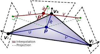 |
| Figure 3: Illustration of the Phong tessellation method. |
Now, by defining $\boldsymbol{\pi}_i(\mathbf{q}) = \mathbf{q} - \left( (\mathbf{q} - \mathbf{p}_i) \cdot \mathbf{n}_i ) \right)\mathbf{n}_i$ as the projection operation we can compute the final position of a vertex $\mathbf{p}^*$ given its barycentric coordinates $(u,v,w)$ as:
\[\begin{align} \mathbf{p}^{*}(u,v) &= u^{2}\mathbf{p}_i + v^{2}\mathbf{p}_{j}+ w^{2}\mathbf{p}_k + uv (\boldsymbol{\pi}_i(\mathbf{p}_j) + \boldsymbol{\pi}_j(\mathbf{p}_i)) \\&+ vw(\boldsymbol{\pi}_j(\mathbf{p}_k) + \boldsymbol{\pi}_k(\mathbf{p}_j)) + wu(\boldsymbol{\pi}_k(\mathbf{p}_i) + \boldsymbol{\pi}_i(\mathbf{p}_k)) \end{align}\]
GPU implementation
Implementing Phong tessellation is pretty straightforward if you've understood the PN triangle implentation. I'll just give the code, but won't comment it.
Tessellation control:
#version 420 core

// Phong tess patch data
struct PhongPatch
{
 float termIJ;
 float termJK;
 float termIK;
};

uniform float uTessLevels;

layout(vertices=3) out;

layout(location = 0)   in vec3 iNormal[];
layout(location = 1)   in vec2 iTexCoord[];

layout(location=0) out vec3 oNormal[3];
layout(location=3) out vec2 oTexCoord[3];
layout(location=6) out PhongPatch oPhongPatch[3];

#define Pi  gl_in[0].gl_Position.xyz
#define Pj  gl_in[1].gl_Position.xyz
#define Pk  gl_in[2].gl_Position.xyz

float PIi(int i, vec3 q)
{
 vec3 q_minus_p = q - gl_in[i].gl_Position.xyz;
 return q[gl_InvocationID] - dot(q_minus_p, iNormal[i])
                           * iNormal[i][gl_InvocationID];
}

void main()
{
 // get data
 gl_out[gl_InvocationID].gl_Position = gl_in[gl_InvocationID].gl_Position;
 oNormal[gl_InvocationID]   = iNormal[gl_InvocationID];
 oTexCoord[gl_InvocationID] = iTexCoord[gl_InvocationID];

 // compute patch data
 oPhongPatch[gl_InvocationID].termIJ = PIi(0,Pj) + PIi(1,Pi);
 oPhongPatch[gl_InvocationID].termJK = PIi(1,Pk) + PIi(2,Pj);
 oPhongPatch[gl_InvocationID].termIK = PIi(2,Pi) + PIi(0,Pk);

 // tesselate
 gl_TessLevelOuter[gl_InvocationID] = uTessLevels;
 gl_TessLevelInner[0] = uTessLevels;
}
Tessellation evaluation:
#version 420 core

// Phong tess patch data
struct PhongPatch
{
 float termIJ;
 float termJK;
 float termIK;
};

uniform float uTessAlpha;
uniform mat4  uModelViewProjection;

layout(triangles, fractional_odd_spacing, ccw) in;

layout(location=0) in vec3 iNormal[];
layout(location=3) in vec2 iTexCoord[];
layout(location=6) in PhongPatch iPhongPatch[];

layout(location=0) out vec3 oNormal;
layout(location=1) out vec2 oTexCoord;

#define Pi  gl_in[0].gl_Position.xyz
#define Pj  gl_in[1].gl_Position.xyz
#define Pk  gl_in[2].gl_Position.xyz
#define tc1 gl_TessCoord

void main()
{
 // precompute squared tesscoords
 vec3 tc2 = tc1*tc1;

 // compute texcoord and normal
 oTexCoord = gl_TessCoord[0]*iTexCoord[0]
           + gl_TessCoord[1]*iTexCoord[1]
           + gl_TessCoord[2]*iTexCoord[2];
 oNormal   = gl_TessCoord[0]*iNormal[0]
           + gl_TessCoord[1]*iNormal[1]
           + gl_TessCoord[2]*iNormal[2];

 // interpolated position
 vec3 barPos = gl_TessCoord[0]*Pi
             + gl_TessCoord[1]*Pj
             + gl_TessCoord[2]*Pk;

 // build terms
 vec3 termIJ = vec3(iPhongPatch[0].termIJ,
                    iPhongPatch[1].termIJ,
                    iPhongPatch[2].termIJ);
 vec3 termJK = vec3(iPhongPatch[0].termJK,
                    iPhongPatch[1].termJK,
                    iPhongPatch[2].termJK);
 vec3 termIK = vec3(iPhongPatch[0].termIK,
                    iPhongPatch[1].termIK,
                    iPhongPatch[2].termIK);

 // phong tesselated pos
 vec3 phongPos   = tc2[0]*Pi
                 + tc2[1]*Pj
                 + tc2[2]*Pk
                 + tc1[0]*tc1[1]*termIJ
                 + tc1[1]*tc1[2]*termJK
                 + tc1[2]*tc1[0]*termIK;

 // final position
 vec3 finalPos = (1.0-uTessAlpha)*barPos + uTessAlpha*phongPos;
 gl_Position   = uModelViewProjection * vec4(finalPos,1.0);
}
Note
The formulas and the variables in the shaders I introduce stick to the notations of the original articles.
Demo
The demo compares the two methods by rendering the same model. Requires an OpenGL4 compliant GPU.
link
Links / Valuable reads
-
PN Triangles paper
-
Phong Tessellation paper
-
GL_ATI_pn_triangles extension
Related articles:
-
History of hardware tessellation
-
10 Fun things to do with tessellation
-
First Contact with OpenGL 4.0 GPU Tessellation


